| file name | remark | update time |
|---|
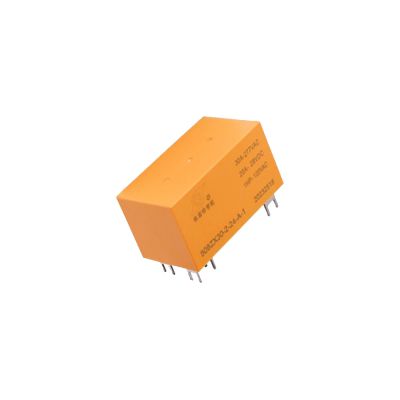
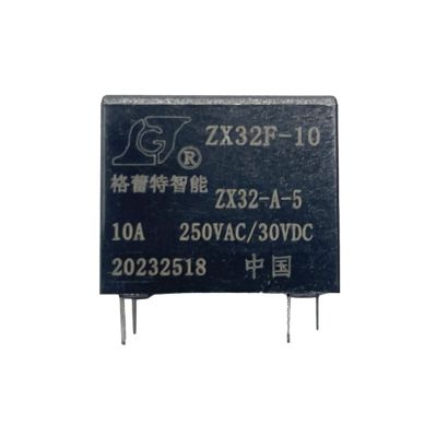
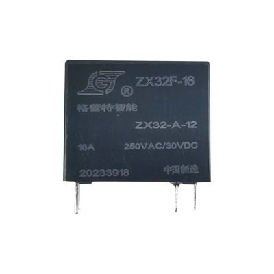
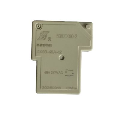
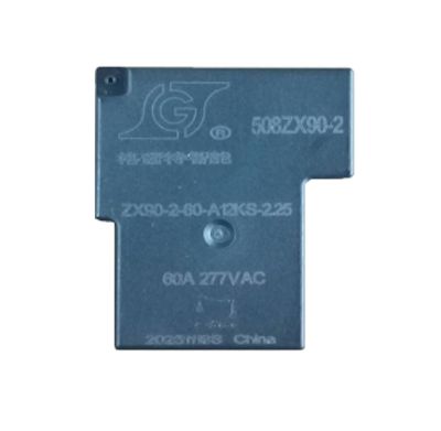
| Appearance | Shell color | Black | Remarks | |||||
| Contact Parameters | Contact form | 1A/1Z | A is of normally open type / Z is of changeover type | |||||
| Contact material | Silver alloy | |||||||
| Initial contact resistance | ≤50mΩ | ≤50mΩ (1A 24VDC) | ||||||
| Contact gap | 1.5~2.0 mm | |||||||
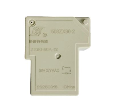
| Contact load (resistive) | 50A/277VAC/240VAC | 50A/30VDC(DC) | ||||||
| Maximum switching voltage | 277VAC | 30VDC | ||||||
| Maximum switching current | 50A | 50A | ||||||
| Maximum switching power | 13850VA | 1500VA | ||||||
| Minimum contact capacity | 100mA/5VDC | 100mA/5VDC | ||||||
| Maximum inrush current | 60A | 60A | ||||||
| Maximum inrush sustained current time | ≤3ms | ≤3ms | ||||||
| Remarks: The above values are initial values. | ||||||||
| Coil Specification Table | Rated voltage VDC | Pull - in voltage ¹ VDC | Release voltage ¹ VDC | Maximum allowable voltage² VDC | Coil resistance Ω/(at 23±1℃) | |||
| 0.9W/I(A) | 1.2W/I(A) | |||||||
| 5 | ≤3.75 | ≥0.25 | 6.5 | 28✖(1±10%)/200mA | 20.8✖(1±10%)/240mA | |||
| 9 | ≤6.75 | ≥0.45 | 11.7 | 90✖(1±10%)/100mA | 67.5✖(1±10%)/140mA | |||
| 12 | ≤9.0 | ≥0.6 | 15.6 | 160✖(1±10%)/75mA | 120✖(1±10%)/100mA | |||
| 18 | ≤13.5 | ≥0.9 | 23.4 | 360✖(1±10%)/50mA | 270✖(1±10%)/67mA | |||
| 24 | ≤18.0 | ≥1.2 | 31.2 | 600✖(1±10%)/40mA | 480✖(1±10%)/50mA | |||
| Environmental Performance Parameters | Operating temperature | -40℃~85℃ | The operating temperature range represents the temperature range within which the relay can continuously operate within the operating voltage range of the coil (no water droplet condensation at low temperatures) | |||||
| Humidity | 45%-85%RH | it complies with IEC 68-2-3 Test Ca. | ||||||
| Storage temperature | -40℃~85℃ | The storage temperature range represents the temperature range within which the relay can be stored without damage (no water droplet condensation at low temperatures). | ||||||
| Mechanical vibration | Vibration durability capacity | 10~55HZ, amplitude 1.0mm | In the non - energized state, the relay is vibrated for 2 hours in each direction of the three axes with an amplitude width of 1.5mm and a frequency of 10 - 55Hz. After the test, there should be no abnormality in the appearance and structure, and the electrical performance should comply with IEC 68-2-6 Test Fc. | |||||
| Vibration resistance (maloperation) | 10~55HZ, amplitude 1.5mm | In the pulled - in/released state, the relay is vibrated for 5 minutes in each direction of the three axes with an amplitude of 1.5mm and a frequency of 10 - 55Hz. The contact misoperation should not exceed 1ms. After the test, the appearance and structure should not be abnormal, and the electrical performance should comply with IEC 68-2-6 Test Fc. | ||||||
| Environmental performance parameters | Mechanical shock | Impact durability capacity | 981m/S2 | The relay withstands two impacts in each of the six directions of the three axes with an acceleration of 981m/s² and an action time of 6 milliseconds. There is no abnormality in the product structure and performance, which complies with IEC 68 - 2 - 27 Test Ea. | ||||
| Impact resistance (malfunction) | 98.1m/S2 | In the energized/released state, the relay withstands two impacts in each of the six directions of the three axes with an acceleration of 98.1m/s² and an action time of 11 milliseconds. The contact misoperation does not exceed 1 millisecond, which complies with IEC 68 - 2 - 27 Test Ea. | ||||||
| Cold resistance | Cold resistance in use | When there is no input state, the relay should be continuously maintained at a temperature of -30 ± 2℃ in the constant temperature box for 2 hours. When conducting the rated voltage test on the operating circuit in the original state, the relay should operate normally. (There is no water droplet condensation phenomenon at low temperature.) | ||||||
| Cold resistance in storage | The relay should be continuously maintained at a temperature of -40 ± 2℃ in the constant temperature box for 72 hours. Then, after removing water droplets at room temperature for 1 - 2 hours, conduct structure, action, insulation impedance, and withstand voltage tests. The results should meet the requirements. (There is no water droplet condensation phenomenon at low temperature.) | |||||||
| Heat resistance | Heat resistance in use | With the rated voltage provided on the operating circuit and the rated current provided at the contact part, the relay should be continuously maintained at a temperature of 85 ± 2℃ for 2 hours. Conduct the relay action test in the original state, and the results must meet the specification requirements. | ||||||
| Heat resistance in storage | The relay should be continuously maintained at a temperature of 85 ± 2℃ in the constant temperature box for 16 hours. After placing it in a normal temperature and humidity state for 1 - 2 hours, conduct structure, action, insulation resistance and withstand voltage tests. The results should meet the requirements. | |||||||
| Moisture resistance | The relay should be continuously maintained at a temperature of 40 ± 2℃ and a relative humidity of 90 - 95% for 48 hours. Then, place it in a normal temperature and humidity state for 1 - 2 hours, and conduct structure, action, insulation impedance, and withstand voltage tests. The results should meet the requirements. | |||||||
| End-foot characteristics | Terminal strength | Apply a horizontal load of 300 grams for 1 minute. After the test, the terminal pins should not have any loosening or bending. | ||||||
| Soldering test | "At a temperature of 260 ± 10℃ for 5 ± 0.5 seconds, immerse the front end of the tinned terminal by 2 - 3mm. The soldering area should reach more than 90%." | |||||||
| Solder heat resistance | "When the terminal pins are immersed in a 350℃ tin furnace for 3 seconds, the relay must meet all electrical and mechanical specification requirements, and its appearance should not change." | |||||||
| Electrical performance parameters | Coil temperature rise | ≤50K | When the relay is no-load, apply rated voltage to the coil. After the temperature stabilizes, measure the temperature rise, which should not exceed 50℃ (excluding the ambient temperature). | |||||
| Contact temperature rise | ≤50K | Apply rated current to the contacts and test after the thermal equilibrium is stable. | ||||||
| Pull-in time (rated voltage) | ≤15ms | Excluding the contact bounce time. | ||||||
| Release time (rated voltage) | ≤10ms | Excluding the contact bounce time. | ||||||
| Insulation resistance | ≥1000MΩ(500VDC) | Between the open contacts, and between the contacts and the coil - Clause 7 in IEC 60255 - 5. | ||||||
| Dielectric Withstand Voltage | Contact - Contact | 1500VAC 1min | 1500VAC, 50/60 Hz (1 minute) - Clause 6 in IEC 60255 - 5. | |||||
| Contact - Coil | 4000VAC 1min | 4000VAC, 50/60 Hz (1 minute) - Clause 6 in IEC 60255 - 5. | ||||||
| Heat resistance and flame retardancy | F-class insulation level | Six - sided Glow - wire | ||||||
| Electrical life | 1×10⁴ | 50A 240VAC pure resistive load, 1S on, 9S off | ||||||
| 5×10⁴ | 40A 240VAC pure resistive load, 1S on, 9S off | |||||||
| 10×10⁴ | 32A 240VAC pure resistive load, 1S on, 9S off | |||||||
| Mechanical life | 1×10⁶ | Number of continuous operations without load | Frequency: 300 times per minute | |||||
| Security authentication | Certification type | test conditions | ||||||
| 0.9W | 1.2W | |||||||
| UL | NO:50A 277Vac/ 50A 277Vac/ 50A 30VDC/ 2HP 240VAC | |||||||
| T∪V | NO:50A 277Vac/ 50A 277Vac/ 50A 30VDC/ 2HP 240VAC | |||||||
| CQC | NO:50A 277Vac/ 50A 277Vac/ 50A 30VDC/ 2HP 240VAC | |||||||
| Remarks: (1) For the loads without specified temperature in the table, the average ambient temperature is room temperature; (2) The detailed test conditions for each load are different, so the actual number of electrical life cycles varies. | ||||||||
|
Structure |
Installation method | PCB board type | ||||||
| Weight | Approximately 30g | |||||||
| Packaging structure | Solder mask type | Sealed type | ||||||
| Sampling inspection standard | GB2828-2012, with General Inspection Level Ⅲ and AQL-0.65 | |||||||
| Security authentication | Incoming material packaging form | The inner packaging is in the form of plastic tube-shaped boxes, and the outer packaging is with sturdy cartons. | ||||||
| Transportation regulations | During the product transportation, attention should be paid to preventing heavy pressure, dropping, moisture, and heat. | |||||||
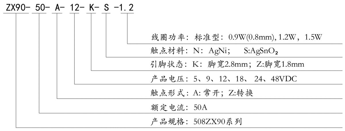
How to order:
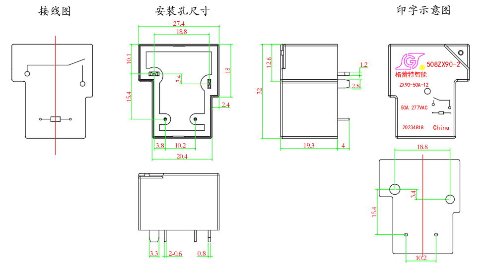
Dimension and Diagram(unit:mm)