| file name | remark | update time |
|---|
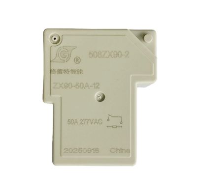
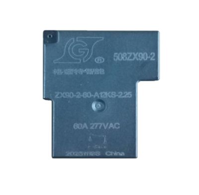
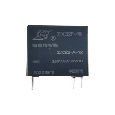
| Appearance | Shell color | black | Remarks | |||||
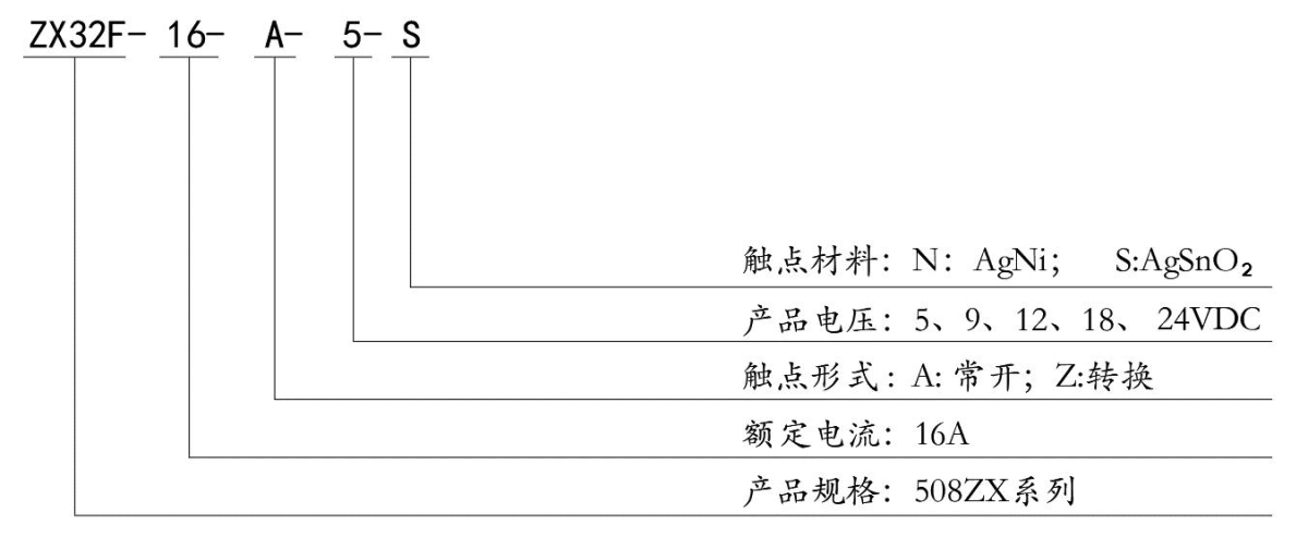
| Contact Parameters | Contact form | 1A/1Z | A is of the normally open type / Z is of the changeover type | |||||
| Contact material | Silver alloy | |||||||
| Contact resistance | ≤100mΩ | ≤100mΩ (1A 6VDC) | ||||||
| Contact gap | Minimum 0.30 mm | |||||||
| Contact load (resistive) | 16A/250VAC | 16V/30VDC | ||||||
| Maximum switching voltage | 250VAC | |||||||
| Maximum switching current | 16A | |||||||
| Maximum switching power | 4000VA | |||||||
| Minimum contact capacity | 1A/6VDC | |||||||
| Maximum inrush current | 78A | |||||||
| Maximum inrush sustained current time | ≤4ms | |||||||
| Remarks: The above values are initial values | ||||||||
| Coil Parameters | Coil rated power consumption | 0.2W/0.45W | ||||||
| Coil rated current | 30mA | |||||||
| Coil Specification Table | Rated voltage VDC | Pull - in voltage ¹ VDC | Release voltage ¹ VDC | Maximum allowable voltage² VDC | Coil resistance Ω/(at 23±1℃) | |||
| 0.2W | 0.45W | |||||||
| 5 | ≤3.75 | ≥0.25 | 6.5 | 125±10% | 55.5±10% | |||
| 9 | ≤6.75 | ≥0.45 | 11.7 | 405±10% | 180±10% | |||
| 12 | ≤9.0 | ≥0.6 | 15.6 | 720±10% | 300±10% | |||
| 18 | ≤13.5 | ≥0.9 | 23.4 | 1620±10% | 720±10% | |||
| 24 | ≤18.0 | ≥1.2 | 31.2 | 2880±10% | 1280±10% | |||
| Environmental Performance Parameters | Operating temperature | -40℃~105℃ | The operating temperature range represents the temperature range within which the relay can operate continuously within the operating voltage range of the coil (with no water droplet condensation at low temperatures). | |||||
| Humidity | 45%-85%RH | |||||||
| Storage temperature | -40℃~85℃ | The storage temperature range represents the temperature range within which the relay can be stored without damage (with no water droplet condensation at low temperatures). | ||||||
| Mechanical vibration | Vibration durability capacity | 10~55HZ amplitude 1.0mm | In the non - energized state, the relay is vibrated for 2 hours in each direction of the three axes with an amplitude width of 1.0mm and a frequency of 10 - 55Hz. After the experiment, there is no abnormality in the appearance and structure, and the electrical performance meets the specified requirements. | |||||
| Vibration resistance (maloperation) | 10~55HZ amplitude 1.5mm | In the pulled - in/released state, the relay is vibrated for 5 minutes in each direction of the three axes with an amplitude of 1.5mm and a frequency of 10 - 55Hz. The contact misoperation shall not exceed 1ms. After the experiment, the appearance and structure shall not be abnormal, and the electrical performance shall meet the specification requirements. | ||||||
| Environmental performance parameters | Mechanical shock | Impact durability ability | 981m/S2 | The relay can withstand the impact of an acceleration of 981m/s² and a duration of 6 milliseconds in six directions on three axes twice each, and there is no abnormality in the product structure and performance. | ||||
| Impact resistance (malfunction) | 98.1m/S2 | In the energized/released state, the relay can withstand the impact of an acceleration of 98.1m/s² and a duration of 11 milliseconds in six directions on three axes twice each, and the contact misoperation does not exceed 1 millisecond. | ||||||
| Cold resistance | Cold resistance in use | When there is no input state, the relay shall be continuously maintained at a temperature of -30 ± 2℃ in the constant temperature box for 2 hours. When conducting the rated voltage test on the operating circuit in the original state, the relay should operate normally. (There is no water droplet condensation phenomenon at low temperature) | ||||||
| Cold resistance in storage | The relay shall be continuously maintained at a temperature of -40 ± 2℃ in the constant temperature box for 72 hours. Then, after removing water droplets at room temperature for 1 - 2 hours, conduct structure, action, insulation impedance and withstand voltage tests. The results shall meet the requirements (There is no water droplet condensation phenomenon at low temperature). | |||||||
| Heat resistance | Heat resistance in use | With the rated voltage provided on the operating circuit and the rated current provided at the contact part, the relay shall be continuously maintained at a temperature of 85 ± 2℃ for 2 hours. Conduct the relay action test in the original state, and the results must meet the specification requirements. | ||||||
| Heat resistance in storage | The relay shall be continuously maintained at a temperature of 85 ± 2℃ in the constant temperature box for 16 hours. After placing it at normal temperature and humidity for 1 - 2 hours, conduct structure, action, insulation resistance and withstand voltage tests. The results shall meet the requirements. | |||||||
| Moisture resistance | The relay shall be continuously maintained in an environment with a temperature of 40 ± 2℃ and a relative humidity of 90 - 95% for 48 hours. Then, place it at normal temperature and humidity for 1 - 2 hours, and conduct structure, action, insulation impedance and withstand voltage tests. The results shall meet the requirements. | |||||||
| Terminal pin characteristics | Terminal strength | Load 300 grams in the horizontal direction for 1 minute. After the test, the terminal pins shall not have any loosening or bending. | ||||||
| Solder test | "At a temperature of 260 ± 10℃, for a time of 5 ± 0.5 seconds, dip the front end of the tinned terminal by 2 - 3mm, and the tin - coated area shall reach more than 90%." | |||||||
| Solder heat resistance |
"When the terminal pins are immersed in a 350℃ tin furnace for 3 seconds, the relay must meet all electrical and mechanical specification requirements, and its appearance shall not change." |
|||||||
| Electrical performance parameters | Coil temperature rise | ≤35K | When the relay is unloaded, apply rated voltage to the coil. After the temperature stabilizes, measure the temperature rise, which shall not exceed 35℃ (excluding the ambient temperature). | |||||
| Pull-in time (rated voltage) | ≤10ms | |||||||
| Release time (rated voltage) | ≤5ms | |||||||
| Insulation resistance | ≥1000MΩ(500VDC) | Between the open contacts, and between the contacts and the coil | ||||||
| Dielectric Withstand Voltage | Contact - Contact | 1000VAC 1min | 1,000VAC, 50/60 Hz (1 minute) | |||||
| Contact - Coil | 2000VAC 1min | 2,000VAC, 50/60 Hz (1 minute) | ||||||
| Heat resistance and flame retardancy | Insulation class F | Hot wire on six sides | ||||||
| Electrical life | 1×10⁵ | 10A 250Vac/30Vdc | Resistive load, normal temperature conditions; Frequency: 30 times per minute, 占空比:1 秒通 9 秒断 | |||||
| 5×10⁴ | 16A 250Vac/30Vdc | |||||||
| Mechanical life | 1×10⁷ | No load, continuous operation times | Duty cycle: 1 second on and 9 seconds off | |||||
| Security authentication | Certification type | Test conditions | ||||||
| 0.2W | 0.45W | |||||||
| UL | NO:16A 250Vac/30Vdc | NO:16A/10A/5A 250Vac/30Vdc | ||||||
| T∪V | NO:16A 250Vac/30Vdc | NO:16A/10A/5A 250Vac/30Vdc | ||||||
| CQC | NO:16A 250Vac/30Vdc | NO:16A/10A/5A 250Vac/30Vdc | ||||||
| Remarks: (1) For the loads without specified temperature in the table, the average ambient temperature is room temperature; (2) The detailed test conditions for each load are different, so the actual number of electrical life cycles varies. | ||||||||
|
Structure |
Installation method | PCB board type | ||||||
| Weight | Approximately 20g | |||||||
| Packaging structure | Solder mask type | |||||||
| Sampling inspection standard | GB2828-2012, with General Inspection Level Ⅲ and AQL-0.65 | |||||||
| Packaging method | Incoming material packaging form | he inner packaging is in plastic boxes (100 pieces per box), and the outer packaging is in sturdy cartons (2000 pieces per carton). | ||||||
| Transportation regulations | During the product transportation, attention should be paid to preventing heavy pressure, dropping, moisture, and heat. | |||||||
How to order:
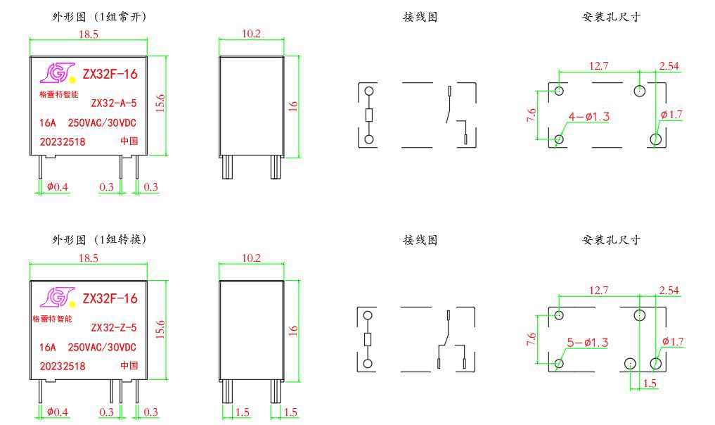
Dimension and Diagram(unit:mm)